Level Control Valve with Bi-Level Vertical Float, WaterMark
750-66-B – Level Control Valve with Bi-Level Vertical Float
The Model 750-66-B Level Control Valve with Bi-Level Vertical Float is a hydraulically controlled, diaphragm actuated, double chambered control valve. The valve is hydraulically powered to fully open at pre-set reservoir low level, and to shut off at pre-set high level regardless of valve differential pressure.
It is the first valve of its design in Australia to be compliant and certified for inclusion in water supply for municipal water and building services.
Reservoir/ Tank filling
- Very low supply pressure
- Low noise generation
- Energy cost critical systems
- Systems with poor water quality
Reservoir/ Tankk outlet
- Distribution routing
- Sewerage “fill and flush” systems
The Model 750-66-B Level Control Valve with Bi-Level Vertical Float is a hydraulically controlled, diaphragm actuated, double chambered control valve. The valve is hydraulically powered to fully open at pre-set reservoir low level, and to shut off at pre-set high level regardless of valve differential pressure.
Features and Benefits
■ Line pressure driven – Independent operation
■ Bi-level hydraulic float control
❑ On/Off service
❑ Low cavitation damage
❑ Suitable for low quality water
❑ Inherent reservoir refreshing
■ Double chamber
❑ Full powered opening and closing
❑ Decreased pressure loss
❑ No throttling noise
❑ Non-slam closing characteristic
❑ Protected diaphragm
■ External installation
❑ Easy access to valve and float
❑ Easy level setting
❑ Less wear and tear
■ Balanced seal disk – High flow capacity
■ In-line serviceable – Easy maintenance
■ Flexible design – Easy addition of features
Major Additional Features
■ Pressure sustaining – 753-66
■ Electric float backup – 750-66-65
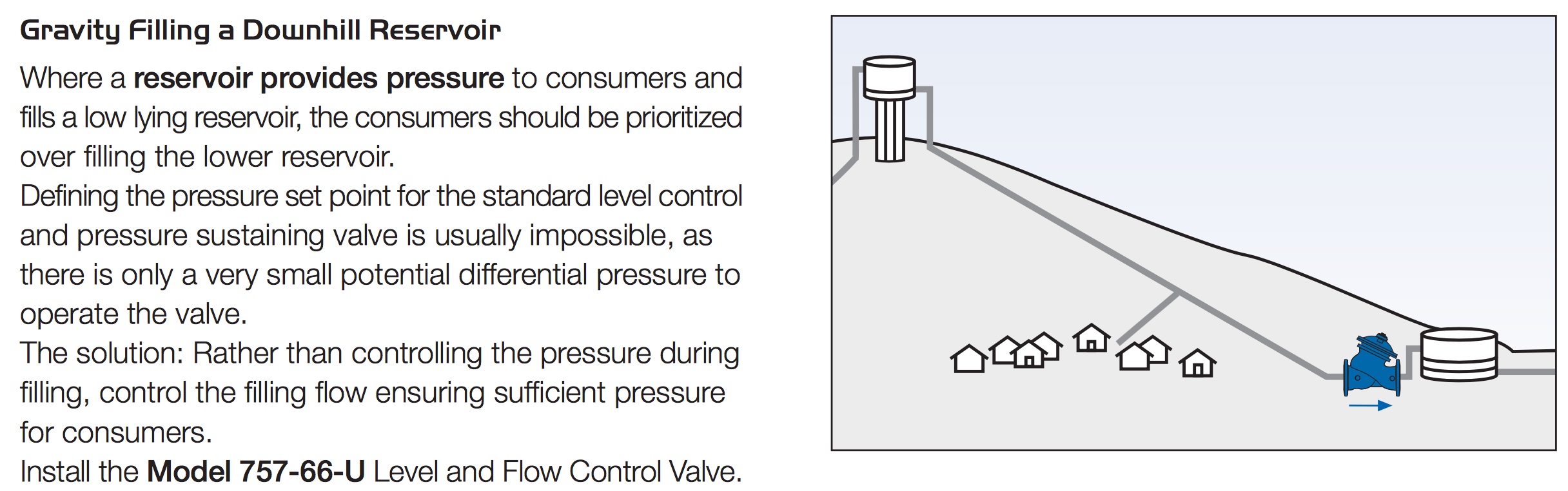
■ Flow control – 757-66-U
■ Closing surge prevention – 750-66-49
■ Level sustaining – 75A-66
Operation
700 Series
Model 750-66-B
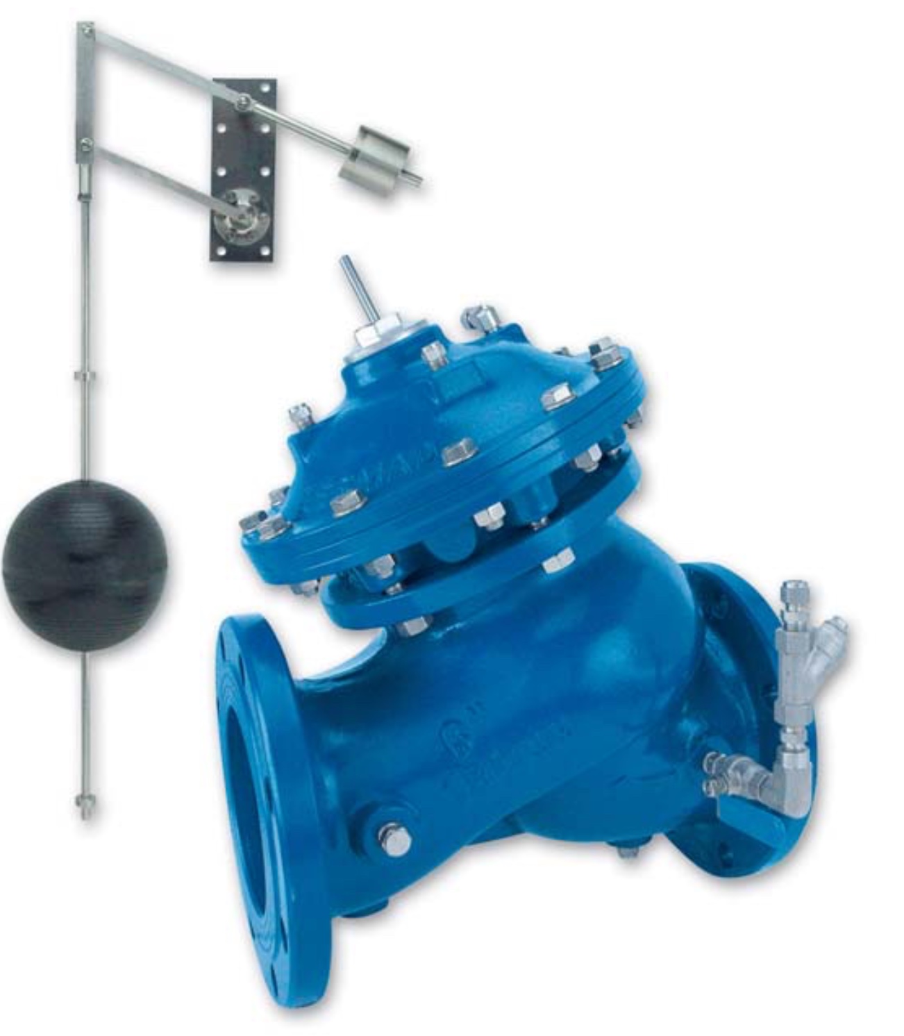
The Model 750-66-B is a float controlled valve equipped with a 4-Way, “last position”, bi-level float pilot assembly.
The float [1] slides along the rod [2]. When the float reaches either the adjustable high [3] or low [4] level stoppers, it either pulls the rod assembly down or pushes it up, switching the float pilot [5] position. When the float is between the adjustable stoppers, the main valve remains in its last position.
At high level, the float pilot applies pressure to the upper control chamber [6], and vents the lower control-chamber [7], powerfully shutting off the main valve.
At low level, the float pilot applies pressure to the lower control chamber, and vents the upper control chamber, powerfully opening the main valve.
For 10” valves and larger, two accelerators [8 & 9] quicken valve response.

Engineer Specifications
The Level Control Valve shall be double chambered to power fully open at pre-set low level, and to shut off at pre-set high level regardless of valve differential pressure.
Main Valve: The main valve shall be a center guided, diaphragm actuated globe valve of either oblique (Y) or angle pattern design. The body shall have a replaceable, raised, stainless steel seat ring. The valve shall have an unobstructed flow path, with no stem guides, bearings, or supporting ribs. The body and cover shall be ductile iron. All external bolts, nuts, and studs shall be Duplex® coated. All valve components shall be accessible and serviceable without removing the valve from the pipeline.
Actuator: The actuator assembly shall be double chambered with an inherent separating partition between the lower surface of the diaphragm and the main valve. The entire actuator assembly (seal disk to top cover) shall be removable from the valve as an integral unit. The stainless steel valve shaft shall be center guided by a bearing in the separating partition. The replaceable radial seal disk shall include a resilient seal and shall be capable of accepting a V-Port Throttling Plug by bolting.
Control System: The control system shall consist of a 4-Way, “last position”, adjustable bi-level, hydraulic float pilot assembly, an isolating cock valve, (for 10” valves and larger: two accelerators), and a filter. All fittings shall be forged brass or stainless steel. The assembled valve shall be hydraulically tested.
Quality Assurance: The valve manufacturer shall be certified according to the ISO 9001 Quality Assurance Standard. The main valve shall be certified as a complete drinking water valve according to NSF, WRAS, and other recognized standards.
Typical Applications
Infrastructure Reservoirs
700 Series
Model 750-66-B
Optimal design of reservoir systems requires specifying a level control valve that reduces pumping costs by minimizing the extra pumping pressure required to operate standard valves.
Even at very low pressure, the Model 750-66-B ensures full opening, maximum flow capacity, and secure closing.
It should be included during the system design phase or with changing needs.


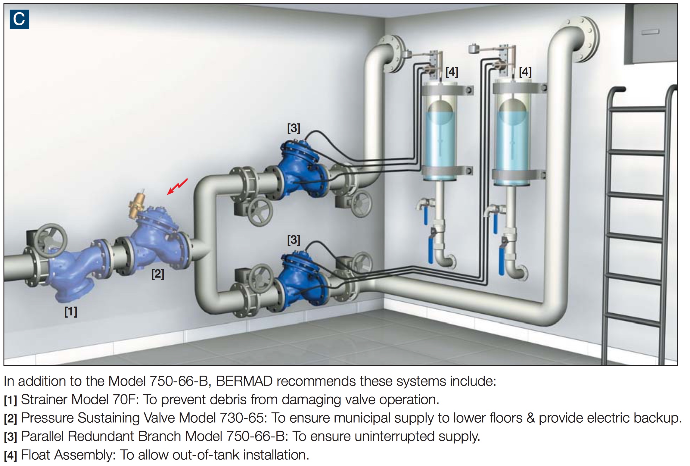
Typical Level Control Systems in High-Rise Buildings
Water supply system design requirements for high-rise buildings present unique issues:
■ Supply cut-off is unacceptable and single source supply is common.
■ Reservoir overflow might be extremely expensive and even dangerous.
■ Reservoirs are often located next to prestigious residential and office space. Extraneous noise and maintenance activities are to be avoided.
■ Most of the occupants of high-rise buildings are completely dependent on the reservoir system of the building for their water needs: potable water, firewater, air conditioning system,
flushing, etc.
■ Pressure for upper floor consumers and for fire protection systems must be prioritized during reservoir filling.
■ As reservoir systems are designed to meet maximum (emergency) consumption, although actual consumption is usually far less, there is a risk of stagnant reservoir water.
The Model 750-66-B backed by BERMAD’S accumulated know-how, addresses these issues and presents appropriate solutions.
Rooftop Reservoirs
Rooftop reservoir level control is attained by electric control of the basement pumps according to reservoir level. As overflow of a rooftop reservoir can cause costly damage, hydraulic backup protection is recommended.
The Model 750-66-B is suited to this function. When open, it presents minimal interference, but when needed, it shuts off securely.
To prioritize pressure to upper floor consumers or fire protection system, install the Model 730 Pressure Sustaining Valve upstream from the Model 750-66-B.

Basement Reservoirs
Basement reservoir design requires consideration of specific issues: ■ Supply cut-off is unacceptable.
■ Reservoir overflow might damage expensive equipment.
■ Noise level* and duration should be limited.
■ Municipal supply pressure might be low.
The Model 750-66-B, as part of the system shown, fulfills these requirements and more.
how to order
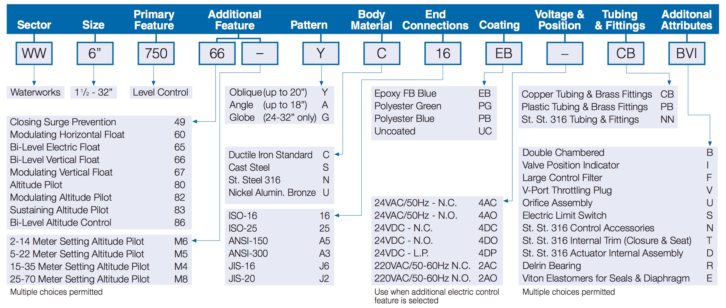
for more information or to order this item, please click here


